
- Insulation
- Posted
Breaking the mould - part II
The previous edition of Construct Ireland featured an article by leading green architect Joseph Little analysing the insulated dry-lined blockwork walls typical of many homes in Irish housing estates, looking particularly at moisture movement within the external walls. Continuing on from that article, Little looks at the implications of several ways of insulating houses of hollow block construction.
This article is the second in a series looking at thermal upgrades to single-leaf walls of existing houses. It compares a range of ways of upgrading masonry single-leaf walls, particularly the ubiquitous hollow block wall, and the impact of those decisions on moisture content, both wind and air-tightness, cost and heating. Future articles will look at various drylining approaches for a range of walls including brick walls of various widths.
A German study of moisture & insulation in single-leaf brick walls
In 1998 Doctor Hartwig Künzel1 of the Fraunhofer Institute in Germany had an excellent paper published on what effects the moisture content of walls. He was particularly focused on single-leaf or ‘massive’ walls and how to upgrade them. He recognised that many brick buildings of architectural or cultural significance can’t be overclad or rendered to reduce the effect of wind-driven rain: “Massive walls exposed to the natural climate without special rain protection show a dynamic moisture equilibrium governed by the alternate events of rain and sunshine,” he said. “The moisture further reduces the rather low insulation level of the wall.”
The paper used the WUFI simulation software for a number of tests but also validated some of these with field tests showing good agreement. He looked first at a brick wall that had previously been drylined in a range of ways, starting the measurements just after its outer surface had been impregnated (to protect against driving-rain)2, and then studied an equivalent wall with two types of external insulation. His conclusions were “that an exterior insulation leads to the drying of the wall, with the drying rate depending on the vapour permeability of the insulation system. An interior insulation, however, results in a rising water content of the wall due to the decreasing masonry temperature…Therefore the interior insulation of exposed walls should be combined with rain protection measures at the facade.”
This author came to similar conclusion in a new study of hollow blocks walls discussed below, as figure 4 shows. Dr Künzel did not specify which siloxane compound he was referring to in his test but Thompson’s Water Seal and various products from Igoe International should give a similar effect. Careful specification from an accredited conservation consultant is advisable.

Mould on the south-east facing un-insulated hollow block wall of a bedroom. The dew point moved over a few weeks towards the inside face of the wall in this underheated room which led to mould growth, as furniture or blinds blocked convection currents that would normally evaporate the resulting moisture
Drylining
Read the full Breaking the mould series
Part 1 - Part 2 - Part 3 - Part 4 - Part 5
The solid line in figure 01, representing the protected but uninsulated brick wall, drops steeply from a high moisture content in the first year (10 per cent) and reaches equilibrium at about 0.8 per cent mid-way through the second year3. The relative speed of this is because vapour can escape out of the wall in two directions and the additional impact of rainwater ingress has been minimised. All the other lines show how drylining inhibits the drying-out of single-leaf walls.
The dotted line represents the effect of the insulating plaster (a thick lime plaster with embedded expanded polystyrene beads), the short dashed line is the effect of fibrous mineral wool drylining and the long-dashed line is for expanded polystyrene board drylining. Each is 60mm thick. In this study no vapour barrier or vapour control layer was used. While the polystyrene has the highest U-value this wall also takes the longest to dry-out to a relatively consistent annual level (10 years). The plaster takes six years and the mineral wool seven. The slower times relate directly to the varying abilities of the insulants to allow vapour move through them into the room. The polystyrene used was 23 times more resistant to vapour diffusion than the mineral wool.
 of unrendered brick walls without and with different types of interior insulation from the month that the outer surface of the brick had been impregnated to protect against driving rain onwards. Source: Künzel ‘98")
Figure 1: The drying out behaviour (in years) of unrendered brick walls without and with different types of interior insulation from the month that the outer surface of the brick had been impregnated to protect against driving rain onwards. Source: Künzel ‘98
 of two different types and thicknesses of external wall insulation Source: Künzel ‘98")
Figure 2: The drying-out time (in years) of two different types and thicknesses of external wall insulation Source: Künzel ‘98
The oscillations in the lines are due to higher quantities of moisture moving into the wall from inside each winter but being able to dry out in both directions each summer. The oscillations are most extreme for the fibrous insulant. This is because it can absorb and release higher quantities of moisture4 while expanded polystyrene allows less vapour through and absorbs almost nothing. The insulating plaster can also absorb and release but in vapour terms will behave more like an extension of the wall itself.

analysis of the corner of a hollow block
wall viewed in plan

Figure 4: Isotherms resulting from
upgrade options in figure 3 |
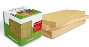
Alternative examples to the insulating plaster which are gaining popularity for use in historic buildings are thick clay plasters and hemp-lime bio-composite plaster. Both are typically applied circa 35mm thick. Ecological Building Systems of Athboy supply the first and Hempire of Clones the second. Both should only be applied to walls that have already been cared for and are dry.
In masonry buildings of all ages, designing for a drier wall (which will consequently have a lower conductivity) with an appropriate drylining build-up is a better goal than focusing only on high-performing insulants, without regard for the masonry’s current or future moisture content, dew point or mould potential. In historic buildings the best approach is to accept a modest improvement at the walls but to seek the biggest increases in energy efficiency in the attic, the heating system, thermal bridging around sliding sash windows and air infiltration.
Externally insulating
Like the compound used to impregnate the brick wall before the drylining study, the external insulation blocks the driving rain and creates a wind-tight seal. Because it also makes the wall warmer and leaves its inner (plastered) surface unclad it gives the masonry the best chance to dry out. The question then becomes which insulant allows this to happen quicker. Again the fibrous insulant scores highest. While both build-ups are non-hygroscopic, its fibrous structure and mineral render surface allow better vapour diffusion than the expanded polystyrene with an acrylic finish.
Interestingly Dr Künzel found little difference in the drying time of different thicknesses. He suggested this might be because thicker, and therefore less diffuse, insulation also made the wall warmer.
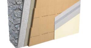
Bear in mind an external insulation system needn’t have an Irish Agrèment Board (IAB) certificate but should have the equivalent European Technical Approval (passed for use in Ireland by the Irish Agrément Board), and be carried out by a trained installer with good track record. Current favourites of this author are the Brillux expanded polystyrene system from Greenspan, and woodfibre insulation systems from NBT (agents Econstruction Products and Lochplace) and Ecological Building Systems: ‘Diffutherm’ and ‘Gutex’ respectively.
Insulation location in hollow blocks walls
Much of Dr Künzel’s work is borne out by this study of hollow block wall upgrades using ‘Therm 5.2’. To our knowledge this is the first study to look at hollow blocks in this way, showing as it does the impact of geometry and insulation position on temperature and energy flow.
Drawing A1 of figure 3 shows a typical uninsulated hollow block wall, plastered on the inside and rendered on the outside. B1 shows the same wall after it has been filled with cavity foam insulation. C1 shows an alternative approach with a drylining system5 and D1 shows the original wall externally insulated6. In all cases the original plaster and render are shown left in place7. Figure 4 shows the thermal impact of these upgrades with isotherms – lines or colours represent areas of the same temperature. In figure 5 the tiny back arrows and colours now represent the rate of energy flow. Note that in this case the blue colour, for instance, means slower energy flow, not a cooler temperature.
In all cases of this test the outside temperature is 0oC and the room is heated to 20oC. The light red colour in detail A2 shows the wall surface is 4.5 degrees cooler than the room air temperature, the yellow colour coming to the surface at the corner is 7.5oC cooler. If a body of air loses half its moisture content every drop of circa 11oC it is no surprise that this area will be a prime spot for damp. It will be necessary for constant warm convection currents within the room to keep mould away here. This is why mould often shows first in a corner cupboard or behind a bed pressed to the wall. Walking past any part of this wall a sensitive occupant will be aware of radiating more heat to the wall than they receive back: they will sense its coldness without needing to touch.

Figure 5: Energy flux resulting from
upgrade options in figure 3 |
B2 shows the thermal effect of filling the linked hollows. Note that the computer software fills every single crevice of the blocks’ hollows. This will not happen in reality. As a nod to reality we haven’t filled the smaller hollows which would be hard to locate with a drill.8 The more undulating shape of the isotherms at the wall surface now reflects the greater difference in thermal performance at the connecting concrete webs compared to the filled hollows. Normal surface temperature registers as varying between 2.5 – 3.0oC, and the corner 6oC, cooler than room temperature – a long way from ideal. The author suspects much of the improvement some people note after getting the hollows filled is actually down to a reduction in infiltration (in other words air leakage) of this dreadful form of construction.
Moving to the drylined and externally insulated walls we can see that the red colour is now continuous. The white colour (a thin line in C2 and a larger area in D2) shows that the surface of the wall is now at room temperature and only the very tip of the corner is 1.0oC cooler. An occupant passing by may be aware of thermal equilibrium: that is of radiating as much heat to the wall as they receive back.
What is fascinating is that it is now graphically very clear what Dr Künzel was saying: external wall insulation aids the drying out of masonry walls, whilst drylining makes them uniformly colder and over time wet. In the external wall insulation the coldest portion of the wall is consigned to the outer few millimetres of insulation and render. Bear in mind that if the source of heat is fully extinguished during a cold spell (due perhaps to the boiler being shut down during a winter trip abroad and also to little solar gain) the owner of the externally insulated wall will know just how much thermal mass they have. It will take a long time to heat up while the drylined house will respond much quicker. Energy flux in hollow block walls
Thermal transmittance, known as U-value (W/m2K), is the rate of energy flow per degree Kelvin through a portion of building fabric. A faster energy flow or flux (W/m2) will contribute to a larger U-value and poorer performance, at least locally.9
It is clear that A3 of Figure 5 above exhibits faster energy flux along its thin concrete webs than through the air gaps or the rest of the concrete. As concrete blocks are highly porous water vapour will be drawn quickly along these narrow paths. What is fascinating is that B3, featuring insulated hollows, is far, far worse. In some places within 25mm, the rate of energy flux changes by a factor of four (circa 20 – 80 W/m2). The best illustration of how differently the concrete webs now act compared to the concrete faces on either side might be to imagine that they have changed to another material entirely with quite different properties – faster energy and thus moisture transfer.
A Lucan-based client of this practice reported coming home to just such a hollow block wall after two weeks of no heat in winter, a year after filling the hollows. He found his south-east facing stairwell wall covered in black mould. Warm convection currents usually kept the dew point in the middle of the wall prior to the change. Now due to a combination of factors including (a) higher energy flux within filled blocks, (b) a week or two of lower temperatures inside the house, and (c) perhaps south-easterly winds with driving rain, a dramatic increase in the room surface’s moisture content resulted. The fact that the centre of the wall now had a reduced ability to dry out via the linked hollows must have further exacerbated the problem.
This all changes in C3 and D3: they both look rather uneventful! Essentially energy flux is quite uniform and fairly slow, somewhere between 0 and 20 W/m2. Another sign of a better, more predictable form of insulation upgrade. In summary it must be evident to the reader that the condition shown in A2 and A3 is unpleasant and should be improved upon for the health and wealth of the occupants. There are many acceptable forms of drylining and external wall insulation to remedy the situation (see C2, C3, D2, D3) but on no account should a homeowner settle for filling the linked hollows (see B3 or B2). If they do they are engaging in an unpredictable, unhealthy and possibly even structurally unstable experiment: buyer beware.
Further penetrations
What is missing in the study above (see A3) is the additional impact of the vertical air flow within the linked hollows of uninsulated blocks. As a basic law of science warm air will rise if allowed to do so. It is therefore inevitable that, even in a hollow block wall that was made totally wind-tight, air would rise within vertically-linked hollows to be replaced by cooler air dropping down. This effect, known as thermal looping, was written about some years ago in Construct Ireland magazine in relation to reduced performance in the insulation of partially-filled cavity walls.
Thermal transmittance calculations (W/m2K) of walls are based on a steady horizontal heat flow from inside to outside. If this thermal looping component is added the heat flow rate must surely accelerate, for the downstairs rooms at least. The result being poorer thermal performance, higher heating bills. The author would be interested if anyone with a thermal-imaging camera could capture this effect by photographing the external walls of an uninsulated hollow block house from the inside, ideally on a cold day with the heating turned up (to accentuate the differences). Ideally the same stretch of external wall would be photographed at its base (in the ground floor room) and at its top (in a first floor room). This could be repeated on more than one external wall or house. Bear in mind if it happens in an uninsulated hollow block wall it will also occur in a drylined one, it just won’t be as easy to capture with a thermal imaging camera (as details A3 and C3 of figure 5 prove).
This effect of thermal looping on thermal performance is compounded if external air, often of lower temperatures and higher humidity levels, can enter into this network of linked hollows. There are at least four reasons as to why this might occur:
- Standard concrete blocks, even 100mm solid blocks, are not air-tight as they are highly porous. The author has felt air passage through the middle of a block at first hand in an airtightness test.
- A wall made of hollow blocks, the latter having an outer concrete face only 40mm wide connected by variable amounts of mortar and covered by a variable amount of render, is going to be hard to make wind-tight even if done with care.
- These buildings were built at a time when there was no awareness of the issues of windtightness on the outside and airtightness on the inside: as the saying goes you can only solve a problem if you know it exists.
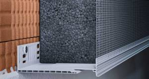
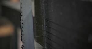
- Penetrations through the outer face, including ‘hole-in-the-wall’ vents, inset telecom or gas-supply boxes, power or telephone cables, and eaves junction are highly likely to introduce external air. See figures 6 and 7 below. The pictures were taken on a typical County Kildare housing estate, built in 2004. Figure 6 shows the recesses made for utility boxes and even an additional chasing route marked out for later cutting. Figure 7 shows how easy it will be for future air paths to go from outside to inside or rise through the linked hollows. How the wall manages to stay upright is an entirely different question!

Utility box recesses in a hollow block wall
The thermal imaging enthusiast mentioned earlier could widen his/her study to include the area of wall above a utility box penetration and below a timber or PVC fascia and soffit. If these items are present it might indicate a more recently-built wall which is also likely to be drylined.
What is interesting is that the choice of thermal upgrade can have a direct impact on the wind-tightness of an existing wall. External wall insulation, as in D1 of figure 3, can close the infiltration routes listed in items (a), (b) and (c) above with its insulation slabs, proprietary high performance render and wind-tightness detailing. A good system is designed to be wind-tight. To see a similar improvement with a drylining-focused thermal upgrade (see C1 of figure 3) it would be necessary to examine each possible point of air ingress and apply an appropriate seal that would affect the outer 40mm wide face: no easy task.
However to get the most benefit the various pathways described in item (d) above also need to be addressed. For instance the wind-tightness of the eaves-wall junction could be examined and upgraded during a routine replacement of fascia and soffit boards, and the utility boxes could be moved to an adjacent blockwork wall or structure. Recent quality housing developments incorporated this utility wall as part of a raised planter or a bin store and looked very well. As such a feature is easy to incorporate during the construction period and has a clear positive impact in terms of wind-tightness, the Construction Industry Federation should insist its members adopt this approach for all new housing. The solution shown in the photographs above cannot be allowed to continue. Unfortunately for those who have houses with utility boxes so mounted it’s an awkward thing to put right, requiring removal of the box and the sealing of the surrounding masonry and pipe ingress points before its replacement. The quick-fix solution of spraying expanding foam into the holes to rear of the box may give an improvement but for how long?
Making the right choice
For those with brick external walls of historic or aesthetic value intent on drylining, first examine the pointing of the mortar joints and see if repair is needed. If it is, make sure you use the right mortar. Check that no downpipes are leaking resulting in localised increases in moisture content. Repairing lime mortar with cement will exacerbate the damage to the bricks and water ingress. Next consider a tested, approved impregnation system that reduces water ingress without reducing vapour diffusion. Both are specialist jobs. Only apply the drylining after this has been completed – at least a few months after.
On no account have the linked hollows of a hollow block wall filled!
It must be clear at this point that the author strongly recommends upgrading houses with hollow block walls with a proprietary external wall insulation system. Fibrous insulants with mineral render coats will allow better vapour diffusion than other systems, but any proprietary external wall insulation system should out-perform drylining a hollow block house given the many shortcomings of hollow block construction.
Financial cost is always an issue in Irish construction projects and can only increase in significance in the current straitened circumstances. This is only right, but our plea to homeowners embarking on an energy-efficient upgrade is that they would give greatest weight to long-term value, long-term costs and long-term benefits. A great example of this can be seen in the comparison of drylining and external wall insulation. Most forms of drylining are cheaper to install on day one, per square metre of prepared surface, than external wall insulation. While this article has discussed in detail hidden long-term costs that must be considered, such as the dependability of the thermal upgrade, mould potential and so on, there are also other hidden financial costs.

Utility box recesses in a hollow block wall
Drylining can require that occupants move out and rent or stay elsewhere, that they put furniture, paintings and other household items in storage (even if still on site) and re-decorate after. External wall insulation on the other hand requires that scaffolding be erected (some external wall insulation installers do this: some leave it to the general builder). For a proper installation with minimum thermal bridging, windows should be unfixed and moved to the outside line of the original wall, drainpipes should also be moved out, roof eave fascias should be adapted and any concrete paving surrounding the house should be cut back to ensure the insulation clads the full height of the relevant external walls. This may sound expensive, but that view may be countered by the shorter construction time, the fact that the occupants can often remain resident, and the fact that the only redecoration needed inside is the cladding of the widened internal window reveals with timber boards. However the final and perhaps most persuasive hidden cost in this comparison, may be the remaining size of the house.
Take a typical Dublin 3-bed semi-detached house with hollow block walls, a floor area of circa 100m2 and overall internal dimensions of 10m x 5m. It has an external wall perimeter of 20m per floor, giving 40m over two floors. This excludes the party wall of course. Assume the external walls are built of hollow block with sand-cement internal plaster and pebbledash outside. A best practice, healthy approach to drylining these walls (to achieve the 0.27 U-value target of the Home Energy Saving scheme) would be to use 80mm of Warmcell 100 or equivalent blown cellulose insulation (λ-value of 0.035), continuously sealed with an intelligent vapour control layer (to surrounding structure), and a 38mm service zone filled with hemp or sheep’s wool with a plasterboard finish. This buildup can be 130mm thick. The floor area lost would be 40m x 0.13m = 5.2 m2 of lost floor area, which converts to (5.2 x 10.76) 56 ft2. Assuming a conservative average value of e250 per ft2 for residential floor space (the value could be double this in certain parts of the city) means that this lost floor area has a value of e13,988.10
Where the discussion is about insulating inside or outside the deciding question could be “can we afford to lose further value by losing space in a market that’s already falling?” An alternative response to this news, wherein the thinnest or cheapest drylining is selected, would be a mistake if those installations have dubious credentials, don’t allow a proper air-tight installation, or result in poor thermal bridging or health. As with almost anything it is better to do a little work well than a lot badly.
One caveat: external wall insulation may not always suit a household with low daytime occupancy. Drylining makes a building thermally lightweight and will result in a quicker heating time which could suit a family of commuters. Externally insulating leaves the original thermally heavyweight structure exposed to the inside. The best way to heat heavyweight structures is to supply constant low-level heat to them. This can be from the free heat of the sun (through good orientation and appropriately-sized windows) and a low temperature radiant heating system, such as can be supplied by underfloor heating or skirting radiators. Remember, heavyweight building fabric can store cold just as well as warmth.
Finally, the right thermal upgrade and heating system are those that suit your specific lifestyle and your house’s construction while safeguarding health and the greater environment on into the future.
1 Künzel, H.M., ‘Effect of interior and exterior insulation on the hygrothermal behaviour of exposed walls’, Materials and Structures, Vol. 31 (March 1998), pp 99-103
2 The rain protection used is a particular siloxane compound.
3 The German standards regard 1.5 per cent as a normal moisture content of factory-delivered bricks, so this level of drying-out is very healthy.
4 Too much moisture and the mineral wool will collapse, whereas a natural fibrous insulant such as hemp wool, sheep’s wool or a woodfibre batt will withstand far higher quantities.
5 The drylining system shown has woodfibre insulation boards fixed to the original plastered wall, an air-tightness membrane, a services zone filled with hemp wool, then plasterboard.
6 A system with expanded polystyrene is shown here.
7 Note only one or two external wall insulation systems can clad over pebbledash, others need the dash removed first.
8 The author can’t help but shudder at the idea of an insulation installer riddling the 40mm thick concrete outer face of the hollow block wall with a close matrix of drilled holes. Imagine parts of the rear portion of that face spalling away under the action of the drill thereby weakening these thin structures further. No homeowner could want that.
9 Blue here represents 0 – 20 W/m2, green: 20 – 40, yellow: 40 – 60, red: 60 - 80 and white: 80 – 100 W/m2.
10 The author is grateful to Jay Stuart of DW Ecoco for persuading him over a cool draught beer that the financial impact of lost space needed to be highlighted here.
Correction: the U-value of a hollow block
“Breaking the mould” was the title of an article by Joseph Little published in the March-April 2009 edition of Construct Ireland (Issue 6, Volume 4) focusing on healthy building and refurbishment. On page 71 of that article there was an error in that a thermal resistance value for hollow blocks of 0.21 m2K/W was referred to as a thermal conductivity value (0.21 W/mK) instead. This necessarily changes the resulting calculations and the author’s conclusions in that particular paragraph of the article. As it happens the author was in good company in making this mistake. A quick check reveals that Roadstone and Hanlon Concrete, for instance, also quote this thermal resistance but give units of thermal conductivity alongside it in their recent brochures.
Similarly Technical Guidance Document L (2005 and 2007) quotes the same thermal pesistance (on p56 of TGD L (2007) but gives the units for thermal transmittance (or U-value), W/m2K.
In an effort to finally clarify the real thermal Resistance, thermal conductivity and thermal transmittance of hollow blocks Joseph Little Architects are making their revised calculations freely available at www.josephlittlearchitects.com and would encourage those thermally upgrading hollow block walls to use these figures.
Read the full Breaking the mould series
- Articles
- Design Approaches
- Breaking the mould: part two
- moisture movement
- insulation
- hollow block
- drylined blockwork
- cellulose
- home energy saving scheme
Related items
-
 New Ejot profile cuts thermal bridging losses by 25mm insulation equivalent
 -
 Ireland’s first 3D printed homes insulated with clay foam
 -
 Unilin Ireland launches embodied carbon report
 -
 Ecological launches Retro EcoWall for internal wall insulation
 -
 Xtratherm name changes to Unilin
 -
 Ecological Building Systems launch Retro EcoWall for internal wall insulation
 -
 Kore launches low carbon EPS
 -
 Kilsaran gets NSAI cert for EWI to steel frame
 -
 Steico offering free wood fibre insulation samples
 -
 Top 5 questions about specifying structural thermal breaks
 -
 Major new grants for retrofit & insulation announced
 -
 How will we decarbonise heating?